
Arduino Real Time 6 Digit Digital Clock using 2.3" 7 segment display with rtc ds1307
Overview
In this tutorial, we will learn how to make a digital clock using RTC(real time clock) DS1307 ic and 7 segment display with Arduino. Although almost all of the microcontrollers have internal built-in timers and timekeeper, they need to an external power supply. If the power supply goes turn off, the timer will take rest from the beginning. To solve this problem we need to use external RTC and battery. The RTC Ics are low current devices that run for a long time on a single lithium battery.

You can watch the following video below:-
Components Required
The following components are needed for this project.- Arduino Uno
- 2.3" 7 Segment Display (Common Cathode)
- RTC DS1307 IC
- 74HC595 Shift Register
- CD4511 7 segment driver
- 3V Lithium Battery
- 32.768 KHz Crystal Oscillator
- 10K Ohm Resistor
- Battery Holder
- Veroboard
- Some Jumper Wire
Pin Configuration
The following below diagram shows the RTC pinout. |
| Fig: Ds 1307 pinout |
 |
| Fig: 7 Segment Common Cathode |
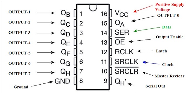 |
| Fig: 74HC595 Shift Register |
 |
| Fig: CD4511 Pinout |
Circuit Schematic
The circuit diagram of the digital clock has been given below:- |
| Fig: Digital Clock Display |
Circuit Description
Next, we will interface Arduino with CD4511 7 segment driver. They will be connected to following below:-
Arduino Uno CD4511 Diver
Pin 5 ------------ Pin 7(In_A)
Pin 6 ------------ Pin 1(In_B)
Pin 7 ------------ Pin 2(In_C)
Pin 8 ------------ Pin 6(In_D)
Pin 5 ------------ Pin 3,4
Pin 6 ------------ Pin 5,8
Arduino and the 74hc595 shift register will be connected to following below:-
Arduino Uno 74HC595 Shift Register
Pin 2 ------------- Pin 11(Clk)
Pin 3 ------------- Pin 12(Latch)
Pin 4 ------------- Pin 24(Data)
5V ------------- Pin 10,16
GND ------------- Pin 8,13
After that, we will interface 7 segment display with CD4511 7 segment driver.
7 Segment display CD4511 Diver
Pin 2(E) ---------------- Pin 9(E)
Pin 3(D) ---------------- Pin 10(D)
Pin 4(C) ---------------- Pin 11(C)
Pin 6(A) ---------------- Pin 13(A)
Pin 7(B) ---------------- Pin 12(B)
Pin 9(F) ---------------- Pin 15(F)
Pin 10(G) ---------------- Pin 14(G)
- The same pin of the six 7 segment displays will be connected to each other.
Arduino and the 74hc595 shift register will be connected to following below:-
7 Segment Display 74HC595 Shift Register
Display 1 Pin 1,5 ------------ Pin 7(OUT_7)
Display 2 Pin 1,5 ------------ Pin 6(OUT_6)
Display 3 Pin 1,5 ------------ Pin 5(OUT_5)
Display 4 Pin 1,5 ------------ Pin 4(OUT_4)
Display 5 Pin 1,5 ------------ Pin 3(OUT_3)
Display 6 Pin 1,5 ------------ Pin 2(OUT_2)
Source Code
The source code of digital clock has been given folowing below:-
 #include <Wire.h>
 #include "RTClib.h"
 RTC_DS1307 rtc;


 int DS_14 = 4;  //data
 int STCP_12 = 3; // latch
 int SHCP_11 = 2; // clock

 int j = 0;
 int k = 0;

 int Digit[6] = {B01111111, B10111111, B11011111, B11101111, B11110111, B11111011};

 void setup() {
  pinMode(STCP_12, OUTPUT); pinMode(DS_14, OUTPUT);
  pinMode(SHCP_11, OUTPUT);
  pinMode(5, OUTPUT); pinMode(6, OUTPUT);
  pinMode(7, OUTPUT); pinMode(8, OUTPUT);

  while (!Serial); // for Leonardo/Micro/Zero

  Serial.begin(9600);
  if (! rtc.begin()) {
   Serial.println("Couldn't find RTC");
   while (1);
  }

  if (! rtc.isrunning()) {
   Serial.println("RTC is NOT running!");
   // following line sets the RTC to the date & time this sketch was compiled
   // rtc.adjust(DateTime(F(__DATE__), F(__TIME__)));
   // This line sets the RTC with an explicit date & time, for example to set
   // January 21, 2014 at 3am you would call:
    rtc.adjust(DateTime(2017, 11, 7, 17, 36, 10));
  }

 }

 void loop() {

  DateTime now = rtc.now();

  int x = now.second();
  int y = now.minute();
  int z = now.hour();

  if (x >= 0 && x < 60)
  {
   Display(0);
   digit1(x);
   delay(3);
   Display(1);
   {
    if (x >= 10 && x < 20) {
     digit1(1);
    }
    else if (x >= 20 && x < 30) {
     digit1(2);
    }
    else if (x >= 30 && x < 40) {
     digit1(3);
    }
    else if (x >= 40 && x < 50) {
     digit1(4);
    }
    else if (x >= 50 && x < 60) {
     digit1(5);
    }
    else digit1(0); delay(3);
   }

   { if (y >= 0 && y < 60)
    {
     Display(2);
     digit1(y);
     delay(2);
     Display(3);
     {
      if (y >= 10 && y < 20) {
       digit1(1);
      }
      else if (y >= 20 && y < 30) {
       digit1(2);
      }
      else if (y >= 30 && y < 40) {
       digit1(3);
      }
      else if (y >= 40 && y < 50) {
       digit1(4);
      }
      else if (y >= 50 && y < 60) {
       digit1(5);
      }
      else digit1(0);
     }
     delay(2);
    }
   }
   if (z >= 0 && z < 24)
   {
    if ((z > 0 && z < 10) || (z > 12 && z < 22))
    {
     Display(4); digit2(z); delay(2);
     Display(5); digit2(10); delay(2);
    }
    else if ((z > 9 && z < 13 ) || (z > 21 && z < 24))
    {
     Display(4); digit2(z); delay(2);
     Display(5); digit2(1); delay(2);
    }
    else if (z == 0)
    {
     Display(4); digit2(z); delay(2);
     Display(5); digit2(1); delay(2);
    }
   }
  }
 }


 void Num(int A, int B, int C, int D)
 {
  digitalWrite(5, A); digitalWrite(6, B); digitalWrite(7, C); digitalWrite(8, D);
 }

 void Display(int x)
 {
  digitalWrite(STCP_12, LOW);
  shiftOut(DS_14, SHCP_11, MSBFIRST, Digit[x]);
  digitalWrite(STCP_12, HIGH);
 }
 void one()
 {
  Num(1, 0, 0, 0);
 }
 void two()
 {
  Num(0, 1, 0, 0);
 }
 void three()
 {
  Num(1, 1, 0, 0);
 }
 void four()
 {
  Num(0, 0, 1, 0);
 }
 void five()
 {
  Num(1, 0, 1, 0);
 }
 void six()
 {
  Num(0, 1, 1, 0);
 }
 void seven()
 {
  Num(1, 1, 1, 0);
 }
 void eight()
 {
  Num(0, 0, 0, 1);
 }
 void nine()
 {
  Num(1, 0, 0, 1);
 }
 void zero()
 {
  Num(0, 0, 0, 0);
 }

 void digit1(int num)
 {
  switch (num) {
   case 0: zero(); break;   case 1: one();  break;  case 2: two();  break;  case 3: three(); break;  case 4: four();  break;
   case 5: five(); break;   case 6: six();  break;  case 7: seven(); break;  case 8: eight(); break;  case 9: nine();  break;
   case 10: zero(); break;  case 11: one();  break;  case 12: two();  break;  case 13: three(); break;  case 14: four(); break;
   case 15: five(); break;  case 16: six();  break;  case 17: seven(); break;  case 18: eight(); break;  case 19: nine(); break;
   case 20: zero(); break;  case 21: one();  break;  case 22: two();  break;  case 23: three(); break;  case 24: four(); break;
   case 25: five(); break;  case 26: six();  break;  case 27: seven(); break;  case 28: eight(); break;  case 29: nine(); break;
   case 30: zero(); break;  case 31: one();  break;  case 32: two();  break;  case 33: three(); break;  case 34: four(); break;
   case 35: five(); break;  case 36: six();  break;  case 37: seven(); break;  case 38: eight(); break;  case 39: nine(); break;
   case 40: zero(); break;  case 41: one();  break;  case 42: two();  break;  case 43: three(); break;  case 44: four(); break;
   case 45: five(); break;  case 46: six();  break;  case 47: seven(); break;  case 48: eight(); break;  case 49: nine(); break;
   case 50: zero(); break;  case 51: one();  break;  case 52: two();  break;  case 53: three(); break;  case 54: four(); break;
   case 55: five(); break;  case 56: six();  break;  case 57: seven(); break;  case 58: eight(); break;  case 59: nine(); break;
  }

 }
 void digit2(int num)
 {
  switch (num)
  {
   case 0: zero();  break;  case 1: one();  break;  case 2: two();  break;  case 3: three(); break;  case 4: four();  break;
   case 5: five();  break;  case 6: six();  break;  case 7: seven(); break;  case 8: eight(); break;  case 9: nine();  break;
   case 10: zero(); break;  case 11: one();  break;  case 12: two();  break;  case 13: one();  break;  case 14: two();  break;
   case 15: three(); break;  case 16: four(); break;  case 17: five(); break;  case 18: six();  break;  case 19: seven(); break;
   case 20: eight(); break;  case 21: nine(); break;  case 22: zero(); break;  case 23: one();  break;  case 24: two();  break;
  }

 }
The RTC library Download link : https://github.com/adafruit/RTClib


No comments