
3 wire Lcd Control using 74Hc595 Shift resister with Arduino
Overview

You can watch the following video below:-
Components Required
The required components list for this project given below:-
- Arduino Uno
- 16*2 LCD Display
- 74HC595 Shift Register
- 10k Potentiometer
- 220-ohm Resistor
- Bread Board
- Some Connecting Wire
LCD Pinout
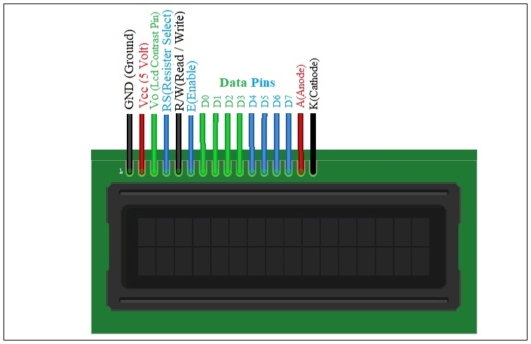
The LCD display pin configuration is given below diagram:-
 |
| Fig: Lcd pin diagram |
74hc595 Shift Register Pinout
Shift register 74hc595 pinout given below diagram:-
 |
| Fig: 74hc595 pinout |
Circuit Diagram
The circuit schematic of LCD interfacing with 74hc595 shift register using Arduino given below:-
 |
| Fig: 3 wire Lcd Control using 74Hc595 Shift resister with Arduino |
Circuit Description
The first pin of LCD from left is Gnd pin which will connect with Arduino ground pin. Next LCD pin 5 (R/W) and 16 (cathode) will also go to ground. The second pin of LCD is Vcc which connect with Arduino +5V. The anode pin 16 of LCD operated on 5V, a 220-ohm resistor should be connected in series to this pin. Next comes to the VEE (Pin 3) which is LCD contrast adjustment pin that will be connected a 10k potentiometer to +5V and ground, with its wiper (output) pin.Shift register pin 16 (Vcc) and pin 10 (MR) will connect with +5V. The ground pin 8 and output enable pin 13 will goes to ground. Next clock pin 11 will connect with Arduino digital pin 13. Similarly, latch pin 12 and data pin 14 will connect with Arduino digital pin 11 and 10 respectively. After that LCD RS pin, 4 will connect with shift register Pin 1. Next Lcd Enable pin 6 will connect with shift register Pin 3. Lcd pin D4 to D7 will connect with shift register pin 4 to 7 respectively.
Lcd pin D0, D1, D2, D3 and shift register pin 2, 9, 13 have no connection.
Source Code
The Source of three wire LCD display given below:- // include the library code:
#include <ShiftedLCD.h>
#include <SPI.h>
// initialize the library with the number of the sspin
// (or the latch pin of the 74HC595)
LiquidCrystal lcd(8);
void setup() {
// set up the LCD's number of columns and rows:
lcd.begin(16, 2);
// Print a message to the LCD.
lcd.print("hello, world!");
}
void loop() {
// set the cursor to column 0, line 1
// (note: line 1 is the second row, since counting begins with 0):
lcd.setCursor(0, 1);
// print the number of seconds since reset:
lcd.print(millis()/1000);
}
Source code download link: https://github.com/omersiar/ShiftedLCD


No comments